Projects and Workspaces
Creating a Simple Project
To create a simple project go to File > Load Image File.
In the Load Image File(s) dialog box you can:
- Select multiple files by holding down the Shift or Ctrl keys.
- Access a list of recently accessed folders displays in the Go to Folder drop-down list. You can also paste a filepath into this field (which will also update the folder buttons at the top of the dialog box).
To later add additional image or thematic layers go to File > Add Data Layer in the main menu.
Creating a Project using the Source View dialog
The Source View dialog provides users a simple data management area to modify input layer alias, display orders and access information on file details.
To open the dialog choose View > Source View.
![]() Select the Add input layer to project button to load data files, alternatively you can select the files in the Windows File Explorer and drag and drop them to the dialog to import them. You can add image layers, vector and point cloud layers to a new or existing project.
Select the Add input layer to project button to load data files, alternatively you can select the files in the Windows File Explorer and drag and drop them to the dialog to import them. You can add image layers, vector and point cloud layers to a new or existing project.
Furthermore, eCognition project (.dpr) and workspace (.dpj) files can be added by drag and drop.
![]() This button deletes a selected data layer or a whole project (dependent on selection).
This button deletes a selected data layer or a whole project (dependent on selection).
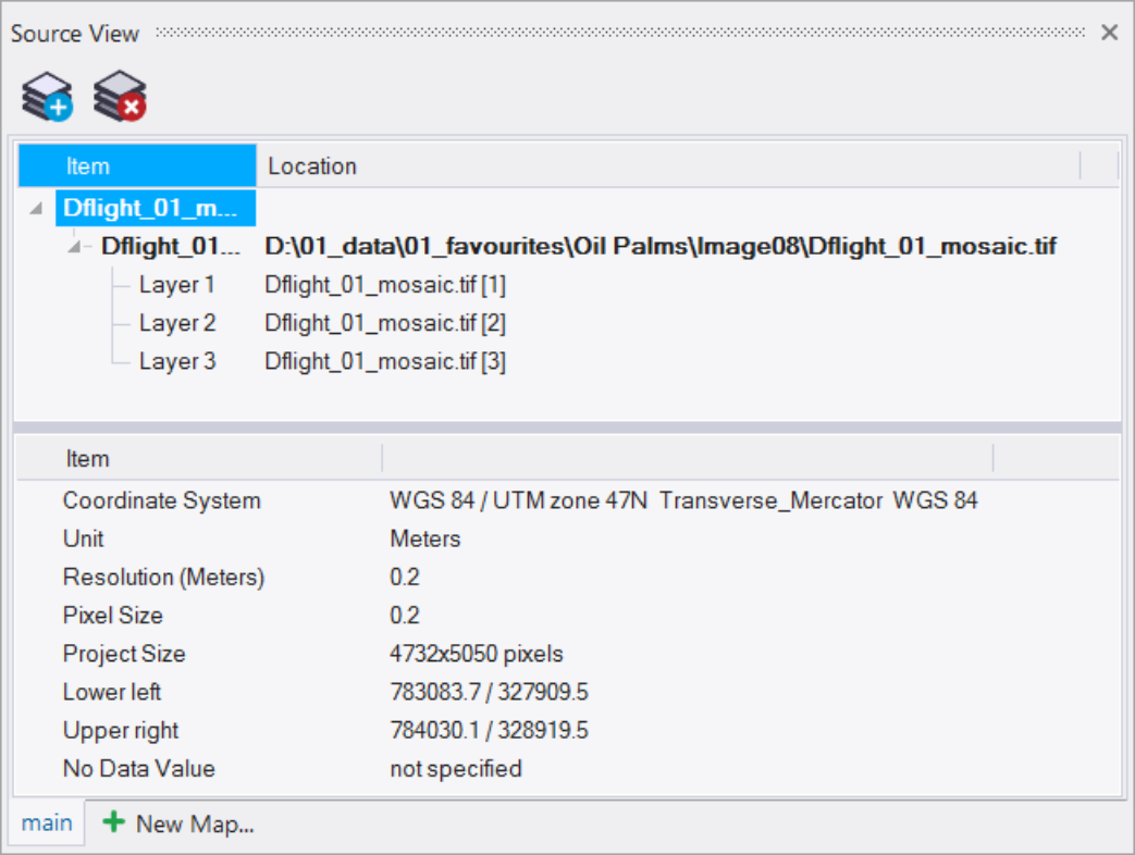
The upper pane of the Source View dialog shows the project name, all data layers loaded, their alias and file paths. On selection of a project file or data file the lower pane shows different details and settings.
If you right click in the upper pane on the project name or a data file you can select one of the following options from the context menu:
- Add New... - add a new data layer
- Delete - delete whole project or data layer (dependent on selection)
- Rename - change the project name or layer alias or map name easily (dependent on selection)
- Project Settings - opens the Modify Project dialog to see or change further project settings
The lower pane of the Source View dialog shows the following details
A) on selection of a project:
- Coordinate System, Unit, Resolution (Unit), Pixel Size, Project Size, Lower left, Upper right, No Data Value
B) on selection of a data file:
- image data
- Type, Name, Location, Size, Lower left, Upper right, Unit, Resolution, Data type, No Data Value
- point cloud data
- Type, Name, Location, Size, Lower left, Upper right, Unit, Resolution, Data type, Number of points, No Data Value
- vector data
- Type, Name, Location, Attribute table, Size, Lower left, Upper right, Unit, Resolution, Point size for rasterization
 Use this option to add new maps to your project. Once you have added new maps, you can switch between their properties using the tabs at the bottom of this dialog.
Creating a Project with Predefined Settings
When you create a new project, the software generates a main map representing the image data of a scene. To prepare this, you select image layers and optional data sources like thematic layers or metadata for loading to a new project. You can rearrange the image layers, select a subset of the image or modify the project default settings. In addition, you can add metadata.
An image file contains one or more image layers. For example, an RGB image file contains three image layers, which are displayed through the Red, Green and Blue channels (layers).
Open the Create Project dialog box by going to File > New Project (for more detailed information on creating a project, refer to The Create Project Dialog Box). The Import Image Layers dialog box opens. Select the image data you wish to import, then press the Open button to display the Create Project dialog box.
File Formats
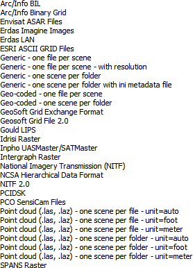
Opening certain file formats or structures requires you to select the correct driver in the File Type drop-down list.
Then select from the main file in the files area. If you select a repository file (archive file), another Import Image Layers dialog box opens, where you can select from the contained files. Press Open to display the Create Project dialog box.
The Create Project Dialog Box
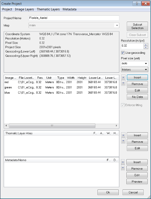
The Create Project dialog box gives you several options. These options can be edited at any time by selecting File > Modify Open Project:
- Change the name of your project in the Project Name field. The Map selection is not active here, but can be changed in the Modify Project dialog box after project creation is finished.
- If you load two-dimensional image data, you can define a subset using the Subset Selection button. If the complete scene to be analyzed is relatively large, subset selection enables you to work on a smaller area to save processing time.
- If you want to rescale the scene during import, edit the scale factor in the text box corresponding to the scaling method used: resolution (m/pxl), magnification (x), percent (%), or pixel (pxl/pxl).
- To use the geocoding information from an image file to be imported, select the Use Geocoding checkbox.
- For feature calculations, value display, and export, you can edit the Pixels Size (Unit). If you keep the default (auto) the unit conversion is applied according to the unit of the coordinate system of the image data as follows:
- If geocoding information is included, the pixel size is equal to the resolution.
- In other cases, pixel size is 1.
In special cases you may want to ignore the unit information from the included geocoding information. To do so, deactivate Initialize Unit Conversion from Input File item in Tools > Options in the main menu
- The Image Layer pane allows you to insert, remove and edit image layers. The order of layers can be changed using the up and down arrows
- If you use multidimensional image data sets, you can check and edit multidimensional map parameters (see Editing Multidimensional Map Parameters) .
- If you load two-dimensional image data, you can set the value of those pixels that are not to be analyzed. Select an image layer and click the No Data button to open the Assign No Data Values dialog box.
- If you import image layers of different sizes, the largest image layer dimensions determine the size of the scene. When importing without using geocoding, the smaller image layers keep their size if the Enforce Fitting check box is cleared. If you want to stretch the smaller image layers to the scene size, select the Enforce Fitting checkbox.
- Thematic layers can be inserted, removed and edited in the same manner as image layers.
- If not done automatically, you can load Metadata source files to make them available within the map.
Geocoding and Projection
Geocoding
Geocoding is the assignment of positioning marks in images by coordinates. Typically, available geocoding information is automatically detected: if not, you can enter coordinates manually. Images without geocodes create automatically a virtual coordinate system with a value of 0/0 at the upper left and a unit of 1 pixel. For such images, geocoding represents the pixel coordinates instead of geographic coordinates.
eCognition can reproject raster image layers and vector layers. If the coordinate system is supported, coordinates from inserted files are detected automatically. If the information is not included in the image file but is nevertheless available, you can edit it manually.
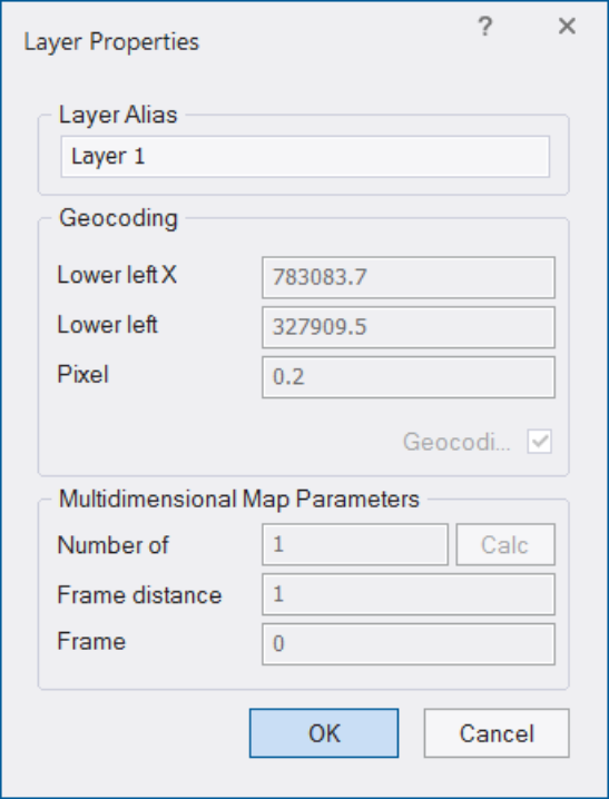
After importing a layer in the Create New Project or Modify Existing Project dialog boxes, double-click on a layer to open the Layer Properties dialog box. To edit geocoding information, select the Geocoding check box. You can edit the following:
- x coordinate of the lower left corner of the image
- y coordinate of the lower left corner of the image
- Pixel size defining the geometric resolution
Assign Projection
If the coordinate system of a dataset is unknown or incorrect you can use this tool to assign a projection (Tools> Assign Projection), under the precondition that you know the projection information.
Existing information on the coordinate system stored in the dataset will be overwritten. This tool does not reproject data and or perform any calculations. To reproject data open the dialog Tools > Reproject Data.
Supported data formats are tif for image data, shapefile for vector data and point clouds in LAS and LAZ formats.
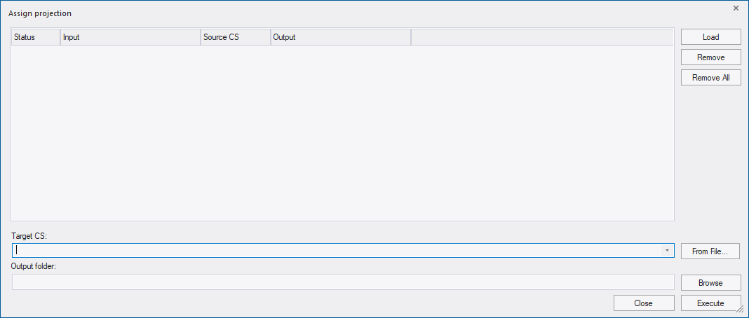
First step is to add the data to the dialog by clicking the Load button.
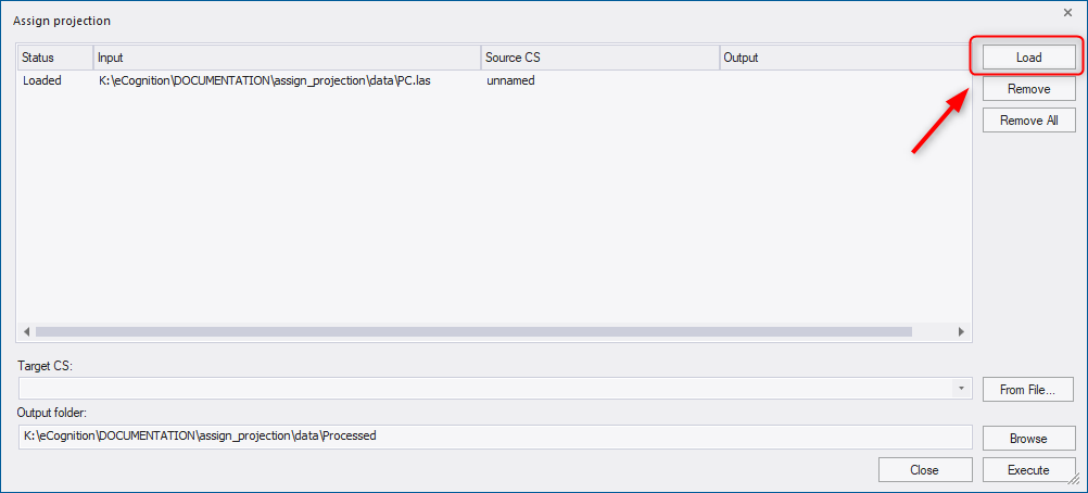
Following information is displayed for each file:
- Status - returns the current status of the input file:
- Loaded - data layer has been successfully added
- Processing - defined projection is being assigned
- Canceled- projection assignment has been interrupted by user
- Finished - defined projection has been successfully assigned to the data
- Input - path to file location
- Source CS - coordinate system of the input file
- Output - ouput path for the processed file
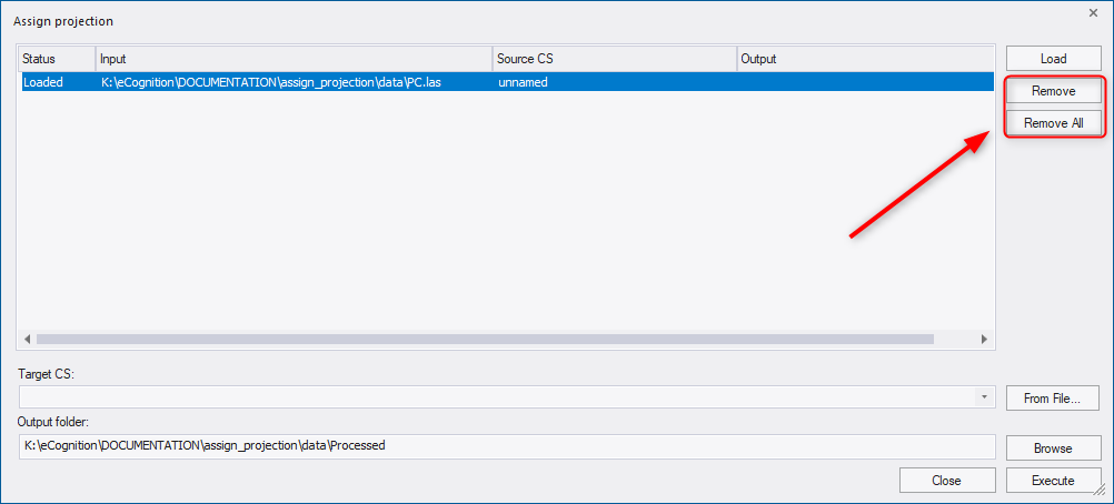
To remove a data file from the list, select the file and press the Remove button. To remove all files from the list, press the Remove All button. These two functionalities do not delete the file, the file will be just unloaded from the list of this Assign Projection dialog.
The target coordinate system (Target CS) can be selected or searched from the drop-down list . To search for a coordinate system, start typing a name or an EPSG code of a coordinate system in the field. Alternatively, a target coordinate system can be loaded via file using the From File button to the right of the drop-down.
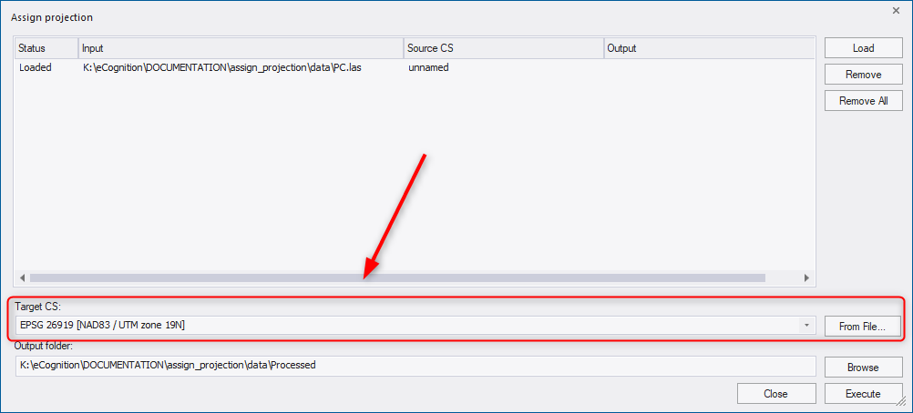
The target coordinate system must be a projected coordinate system. Supported input formats are tif, shp, LAS/LAZ (see also Reprojection tool in following chapter).
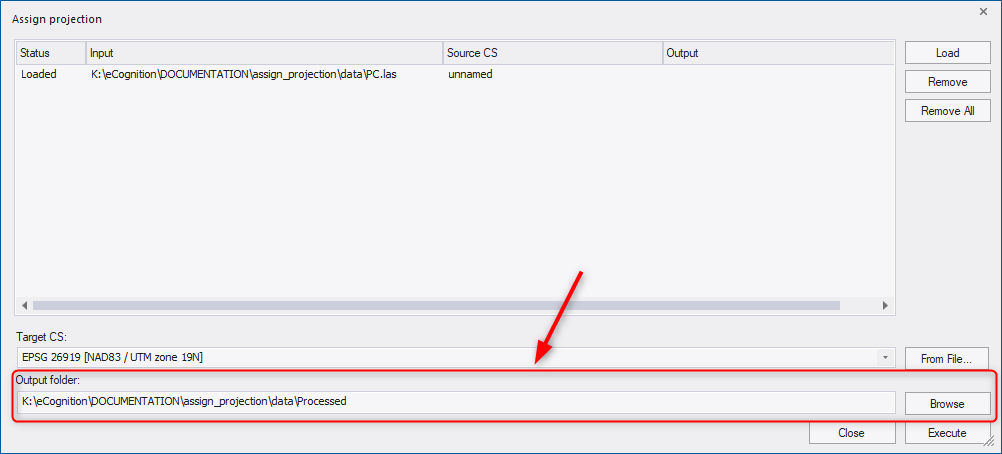
In the Output folder field, the path for files with assigned projection is displayed: by default they are located in a subfolder of the data folder called Processed. (If the data is located in different folders, the default path is the folder of the first loaded dataset). However, you can define the ouput folder using the Browse button or type directly into the Output folder field.
To assign the new projection to the loaded input files, press the Execute button. Then a progress bar appears on the screen indicating the status of processing. When the projection assignment is done an output path appears next to each file in the dialog.
Reproject
For image analysis in eCognition Developer, the data used must belong to the same projected coordinate system. Geographic coordinate systems have different pixel size in X and Y axes resulting in non-square pixels which should be avoided.
This reprojection tool can be used for reprojecting data from a geographic coordinate system to a projected coordinate system or from one projected coordinate system to another if the data are defined on different systems or if you need the results in a coordinate system different from the one of the input data.
To reproject data select Tools > Reproject Data.
Supported data formats are tif for image data and shapefile format for vector data.
Use the Load button to add the data to the Reproject data dialog.
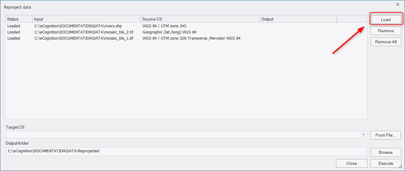
In the dialog you get the following information for each file:
- Status - returns the current status of the input file:
- Loaded - data layer has been successfully added
- Processing - target coordinate system is being reprojected
- Canceled - reprojection has been interrupted by user
- Finished - reprojection has been successfully executed
- Input - the path to the file location
- Source CS - coordinate system of the input file
- Output - path to the reprojected file
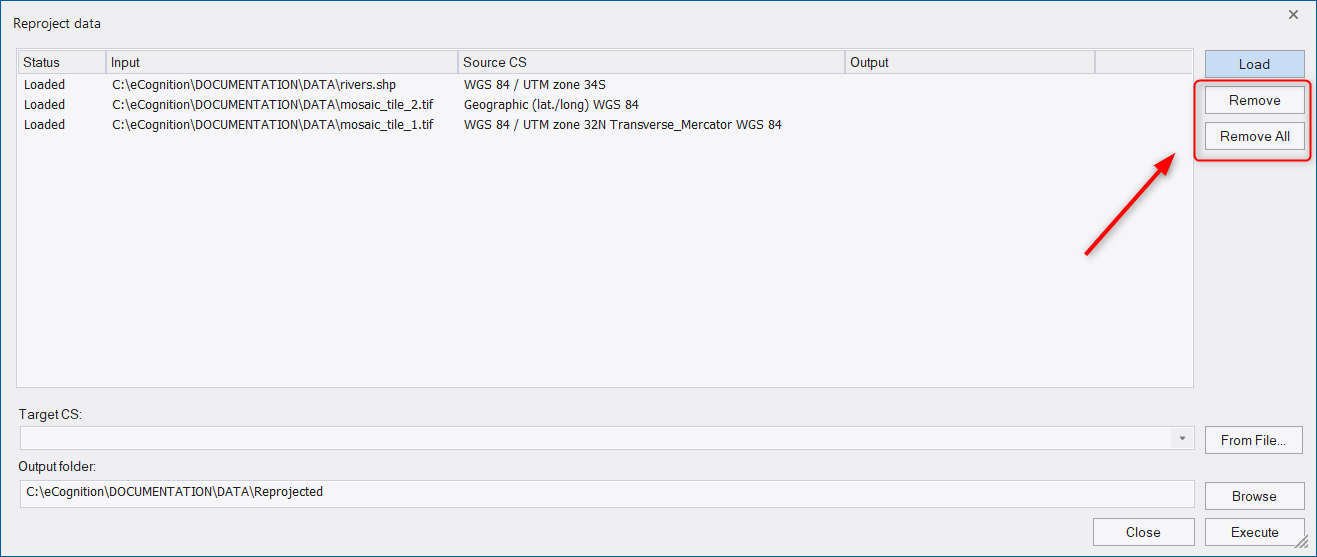
To remove a data file from the list, select the file and press the Remove button. To remove all files from the list, press the Remove All button. These two functionalities do not delete the file, the file will be just unloaded from the list of the Reproject dialog.
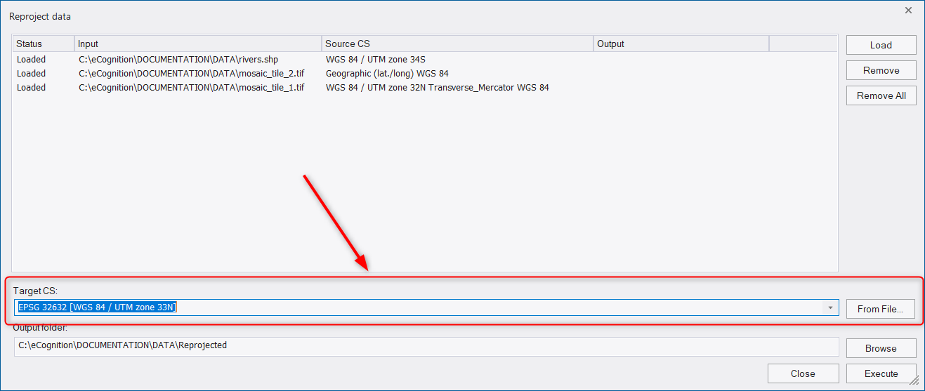
The target coordinate system (Target CS) can be selected or searched from the drop-down list. To search for a coordinate system, start typing a name or an EPSG code of a coordinate system in the field. Alternatively, a target coordinate system can be loaded via file using the From File button to the right of the drop-down.
The target coordinate system must be a projected coordinate system. Supported data formats are TIF for image data and shapefile for the vector data.
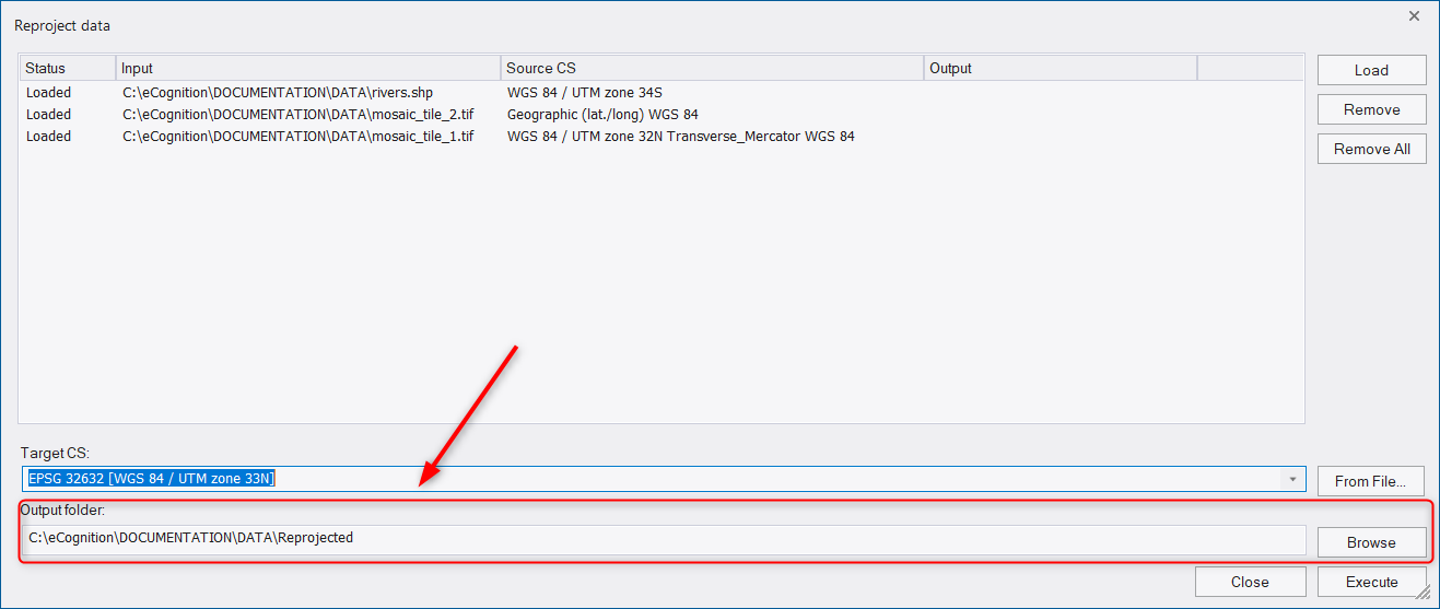
In the Output folder field, the path for reprojected files is displayed: by default they are located in a subfolder of the data folder called Reprojected. (If the data is located in different folders, the default path is the folder of the first loaded dataset). However, you can define the ouput folder using the Browse button or type directly into the Output folder field.
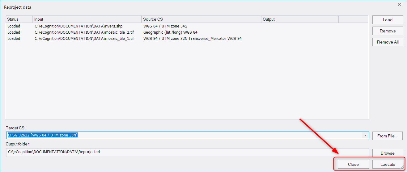
To reproject the loaded input files press the Execute button.
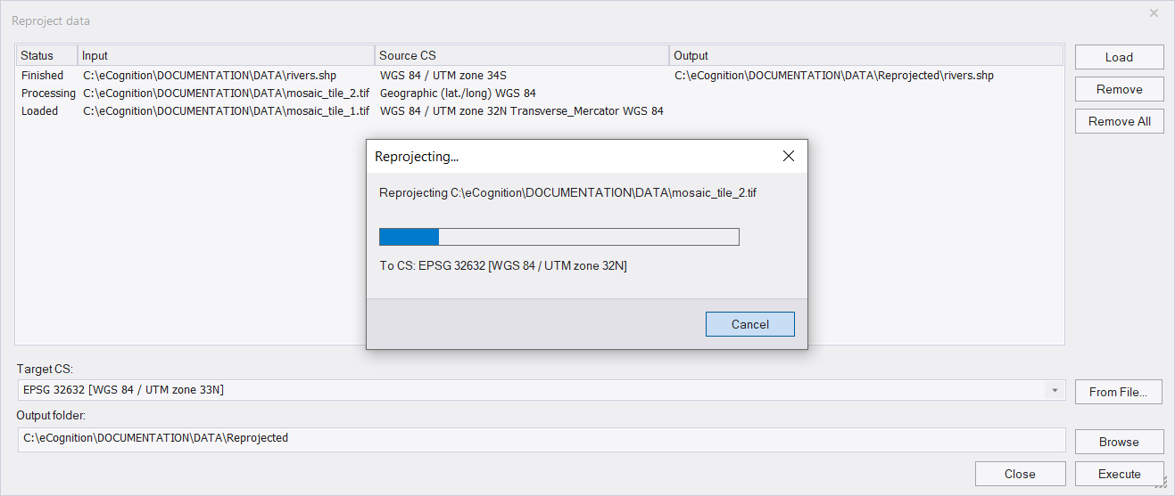
Then a progress bar appears indicating the status of processing. Once the reprojection is applied an output path appears next to each file in the dialog window.
If you add image layers or thematic layers to a project, that are assigned to a geographic coordinate syste, a warning message is prompted that it is recommend to reproject the data. Select one of the following options:
- Continue: add data without reprojection
- Assign projection: assign a projection to the data without reprojecting it
- Re-project: reproject data using the reprojection tool (adds data automatically to the workspace)
- Cancel: do not add the data and exit the dialog
Assigning No-Data Values
No-data values can be assigned to scenes with two dimensions only. This allows you to set the value of pixels that are not to be analyzed. Only no-data-value definitions can be applied to maps that have not yet been analyzed.
No-data values can be assigned to image pixel values (or combinations of values) to save processing time. These areas will not be included in the image analysis. Typical examples for no-data values are bright or dark background areas. The Assign No Data Value dialog box can be accessed when you create or modify a project.
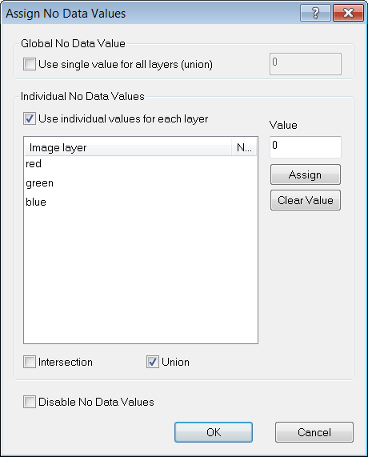
After preloading image layers press the No Data button. The Assign No Data Values dialog box opens:
- Selecting Use Single Value for all Layers (Union) lets you set a single pixel value for all image layers.
- To set individual pixel values for each image layer, select the Use individual Values for Each Layer check box
- Select one or more image layers
- Enter a value for those pixels that are not to be analyzed. Click Assign. For example in the dialog box above, the no data value of Layer 1 is 0.000000. This implies that all pixels of the image layer Layer 1 with a value of zero (i.e. the darkest pixels) are excluded from the analysis. The no data value of Layer 2 is set to 255 in the Value field
- Select Intersection to include those overlapping no data areas only that all image layers have in common
- Select Union to include the no data areas of all individual image layers for the whole scene, that is if a no data value is found in one image layer, this area is treated as no data in all other image layers too
Importing Image Layers of Different Scales
You can insert image layers and thematic layers with different resolutions (scales) into a map. They need not have the same number of columns and rows. To combine image layers of different resolutions (scales), the images with the lower resolution – having a larger pixel size – are resampled to the size of the smallest pixel size. If the layers have exactly the same size and geographical position, then geocoding is not necessary for the resampling of images.
Editing Multidimensional Map Parameters
When creating a new map, you can check and edit parameters of multidimensional maps that represent time series. Typically, these parameters are taken automatically from the image data set and this display is for checking only. However in special cases you may want to change the number, the distance and the starting item of frames. The preconditions for amending these values are:
- The project includes at least two frames.
- The new project has not yet been created or the new map has not yet been saved.
- For changing Frame parameters of time series maps, the width of the internal map has to be five times larger or more than the height.
To open the edit multidimensional map parameters, create a new project or add a map to an existing one. After preloading image layers press the Edit button. The Layer Properties dialog box opens.
- Change Frame parameters only to change the time dimension of a time series map.
Editable parameters are listed in the following table - Multidimensional Map Parameters:
| Parameter | Description | Calc button | Default |
|---|---|---|---|
| Number of frames | The number of two-dimensional images each representing a single film picture (frame) of a scene with time dimension. | Click the Calc button to calculate the rounded ratio of width and height of the internal map. | 1 |
| Frame distance | Change the temporal distance between frames. | (no influence) | 1 |
| Frame start | Change the number of the first displayed frame. | (no influence) | 0 |
Confirm with OK and return to the previous dialog box. After the a with a new map has been created or saved, the parameters of multidimensional maps cannot be changed any more.
Multisource Data Fusion
If the loaded image files are geo-referenced to one single coordinate system, image layers and thematic layers with a different geographical coverage, size, or resolution can be inserted.
This means that image data and thematic data of various origins can be used simultaneously. The different information channels can be brought into a reasonable relationship to each other.
Creating, Saving and Loading Workspaces
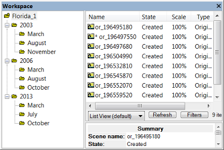
The Workspace window lets you view and manage all the projects in your workspace, along with other relevant data. You can open it by selecting View > Windows > Workspace from the main menu.
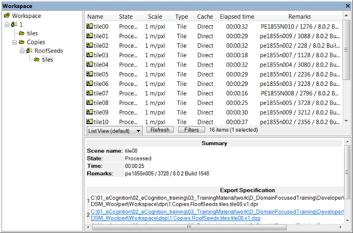
The Workspace window is split in two panes:
- The left-hand pane contains the Workspace tree view. It represents the hierarchical structure of the folders that contain the projects
- In the right-hand pane, the contents of a selected folder are displayed. You can choose between List View, Folder View, Child Scene View and two Thumbnail views.
In List View and Folder View, information is displayed about a selected project – its state, scale, the time of the last processing and any available comments. The Scale column displays the scale of the scene. Depending on the processed analysis, there are additional columns providing exported result values.
Opening and Creating New Workspaces
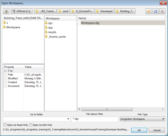
To open a workspace, go to File > Open Workspace in the main menu. Workspaces have the .dpj extension. This function uses the same customized dialog as described for loading an image file (Creating a Simple Project).
Alternatively you can select workspace (.dpj) or project (.dpr) files in the Windows File Explorer and drag and drop them to the workspace window to import them.
To create a new workspace, select File > New Workspace from the main menu or use the Create New Workspace button on the default toolbar. The Create New Workspace dialog box lets you name your workspace and define its file location – it will then be displayed as the root folder in the Workspace window.
If you need to define another output root folder, it is preferable to do so before you load scenes into the workspace. However, you can modify the path of the output root folder later on using File > Workspace Properties.
User Permissions
The two checkboxes at the bottom left of the Open Workspace dialog box determine the permissions of the user who opens it.
- If both boxes are unchecked, users have full user rights. Users can analyze, roll back and modify projects, and can also modify workspaces (add and delete projects). However, they cannot rename workspaces
- If Read-Only is selected, users can only view projects and use History View. The title bar will display ‘(Read Only)’
- If Edit-Only is selected, the title bar will display ‘(Limited’) and the following principles apply:
- Projects opened by other user are displayed as locked
- Users can open, modify (history, name, layers, segmentation, thematic layers), save projects and create new multi-map projects
- Users cannot analyze, rollback all, cancel, rename, modify workspaces, update paths or update results
If a Project Edit user opens a workspace before a full user, the Workspace view will display the status ‘locked’. Users can use the Project History function to show all modifications made by other users.
Multiple access is not possible in Data Management mode. If a workspace is opened using an older software version, it cannot be opened with eCognition Developer at the same time.
Importing Scenes into a Workspace
Before you can start working on data, you must import scenes in order to add image data to the workspace. During import, a project is created for each scene. You can select different predefined import templates according to the image acquisition facility producing your image data.
If you only want to import a single scene into a workspace, use the Add Project command. To import scenes to a workspace, choose File > Predefined Import from the main menu or right-click the left-hand pane of the Workspace window and choose Predefined Import. (By default, the connectors for predefined import are stored in the installation folder under \bin\drivers\import. If you want to use a different storage folder, you can change this setting under Tools > Options > General.)
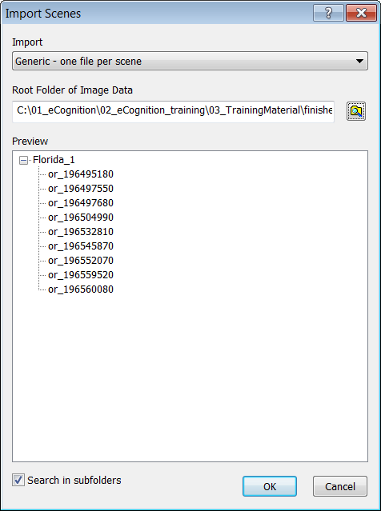
The Import Scenes dialog box opens:
- Select a predefined template from the Import Template drop-down box
- Browse to open the Browse for Folder dialog box and select a root folder that contains image data
- The subordinate file structure of the selected image data root folder is displayed in the Preview field. The plus and minus buttons expand and collapse folders
- Click OK to import scenes. The tree view on the left-hand pane of the Workspace window displays the file structure of the new projects, each of which administrate one scene.
Supported Import Templates
You can use various import templates to import scenes. Each import template is provided by a connector. Connectors are available according to which edition of the eCognition Server you are using.
- Generic import templates - are available for simple file structures of import data. When using generic import templates, make sure that the file format you want to import is supported
- Import templates - provided by connectors are used for loading the image data according to the file structure that is determined by the image reader or camera producing your image data
- Raster stitching templates - creates one project per folder and automatically stitches user defined tiles into a mosaic (second template to select if pixel transparency should be set to 0)
- Customized import templates can be created for more specialized file structures of import data
A full list of supported and generic image formats is available in Supported Raster and Vector Formats
Generic Import Templates
| Import Template (Connector) | Description | File Formats | File Based? | Windows | Linux |
|---|---|---|---|---|---|
| Generic – one file per scene | A scene may consist of multiple image layers. All image layers are saved to one file | All | Yes | Yes | Yes |
| Generic – one scene per folder | All files that are found in a folder will be loaded to one scene | All | Yes | Yes | Yes |
Generic import templates may support additional instruments or image readers not listed here. For more information about unlisted import templates contact Trimble via https://support.ecognition.com/
About Generic Import Templates
Image files are scanned into a workspace with a specific method, using import templates, and in a specific order according to folder hierarchy. This section lists principles of basic import templates used for importing scenes within the Import Scenes dialog box.
- Generic — one file per scene
- Creates one scene per file.
- The number of image layers per scene is dependent on the image file. For example, if the single image file contains three image layers, the scene is created with three image layers.
- Matching Pattern: anyname
- For the scene name, the file name without extension is used.
- Geocoded – one file per scene: Reads the geo-coordinates separately from each readable image file.
- Generic — one scene per folder
- All image layers are taken from all image files.
- Creates a scene for each subfolder.
- Takes all image files from the subfolder to create a scene.
- If no subfolder is available the import will fail.
- The name of the subfolder is used for the scene name.
- Geocoded – one file per scene: Reads the geo-coordinates separately from each readable image file.
Options
Images are scanned in a specific order in the preview or workspace. There are two options:
- Select the check-box Search in Subfolders:
- Files in selected folder and all subfolders
- Takes the first item in current folder
- If this item is a folder, then steps into this folder and continues search there.
- Clear the check-box Search in Subfolders:
- Only files directly in the folder
- Alphabetical ascending
For example, one might import the following images with this folder structure:[selected folder] > [1] > [5] > 1.tif & 8.tif[selected folder] > [1] > [8] > 5.tif[selected folder] > [1] > 3.tif & 7.tif[selected folder] > [3] > 6.tif[selected folder] > 2.tif & 4.tif
Predefined Import Templates
Configuring the Workspace Display
eCognition Developer offers several options for customizing the Workspace.
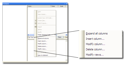
To select what information is displayed in columns, right-click in the pane to display the context menu.
- Expand All Columns will auto fit the columns to the width of the pane. If this is selected, the menu will subsequently display the Collapse All Menus option.
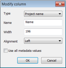
- Selecting Insert Column or Modify Column displays the Modify Column dialog box:
- In Type, select the column you wish to display
- In Name, enter the text to appear in the heading
- In Width, select the width in pixels
- In Alignment, choose between left, right and center
- Press OK to confirm. You can change the position of a column by dragging it with the mouse.
- Select Delete Column to get rid of a column
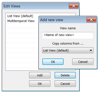
- Modify Views launches the Edit Views dialog box, which lets you save a particular view.
- Use the buttons to add or delete views
- Selecting Add launches the Add New View dialog box. Enter the name of your custom view and select the view on which you wish to base it in the Copy Columns From field.